Patents Directory for Dr. Gary K. Michelson — U.S. Published Patents only
340 patents found - Page 10
| Patent | Abstract |
|---|---|
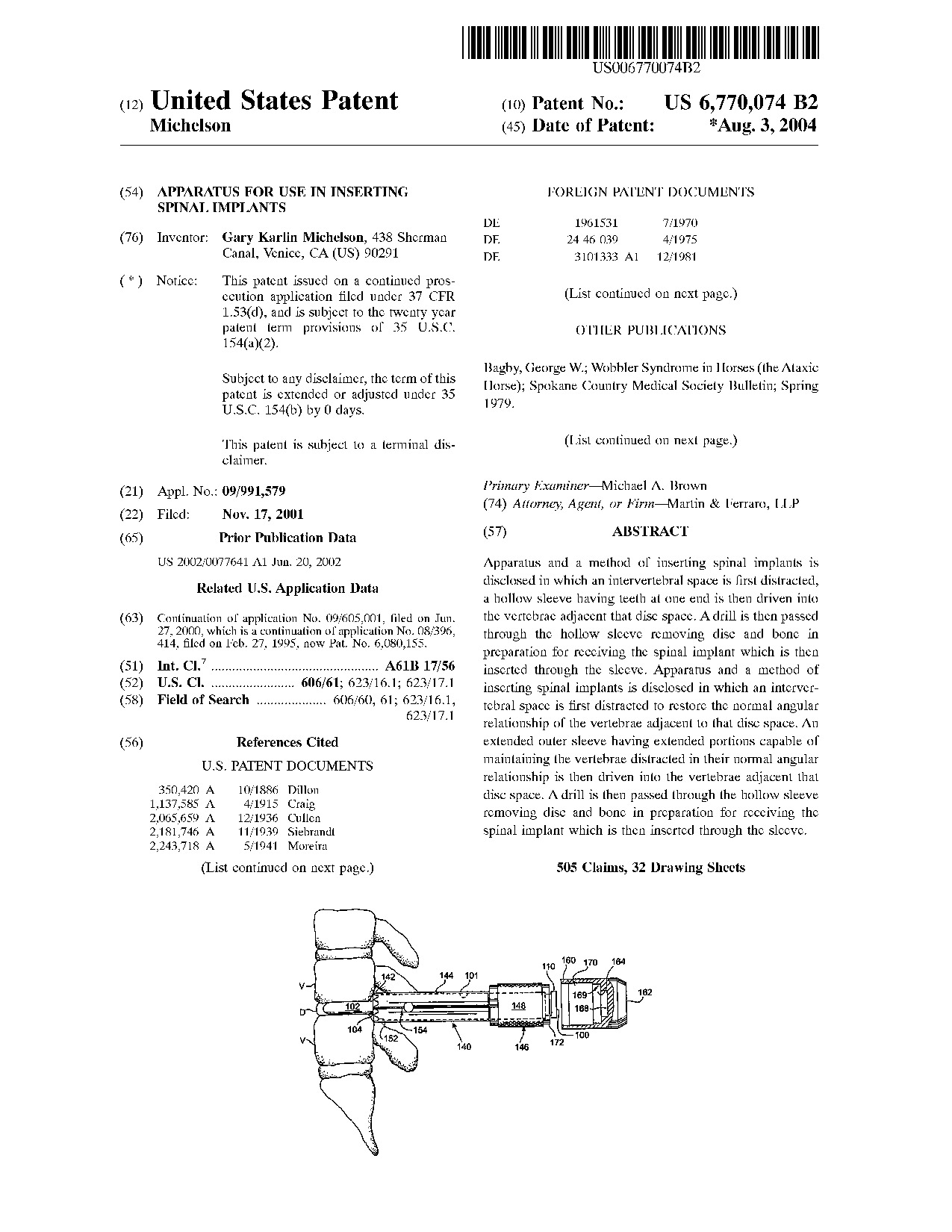 Apparatus for use in inserting spinal implants - Patent 6,770,074 Apparatus for use in inserting spinal implants - Patent 6,770,074
|
Apparatus and a method of inserting spinal implants is disclosed in which an intervertebral space is first distracted, a hollow sleeve having teeth at one end is then driven into the vertebrae adjacent that disc space. A drill is then passed through the hollow sleeve removing disc and bone in preparation for receiving the spinal implant which is then inserted through the sleeve. Apparatus and a method of inserting spinal implants is disclosed in which an intervertebral space is first distracted to restore the normal angular relationship of the vertebrae adjacent to that disc space. An extended outer sleeve having extended portions capable of maintaining the vertebrae distracted in their normal angular relationship is then driven into the vertebrae adjacent that disc space. A drill is then passed through the hollow sleeve removing disc and bone in preparation for receiving the spinal implant which is then inserted through the sleeve.
|
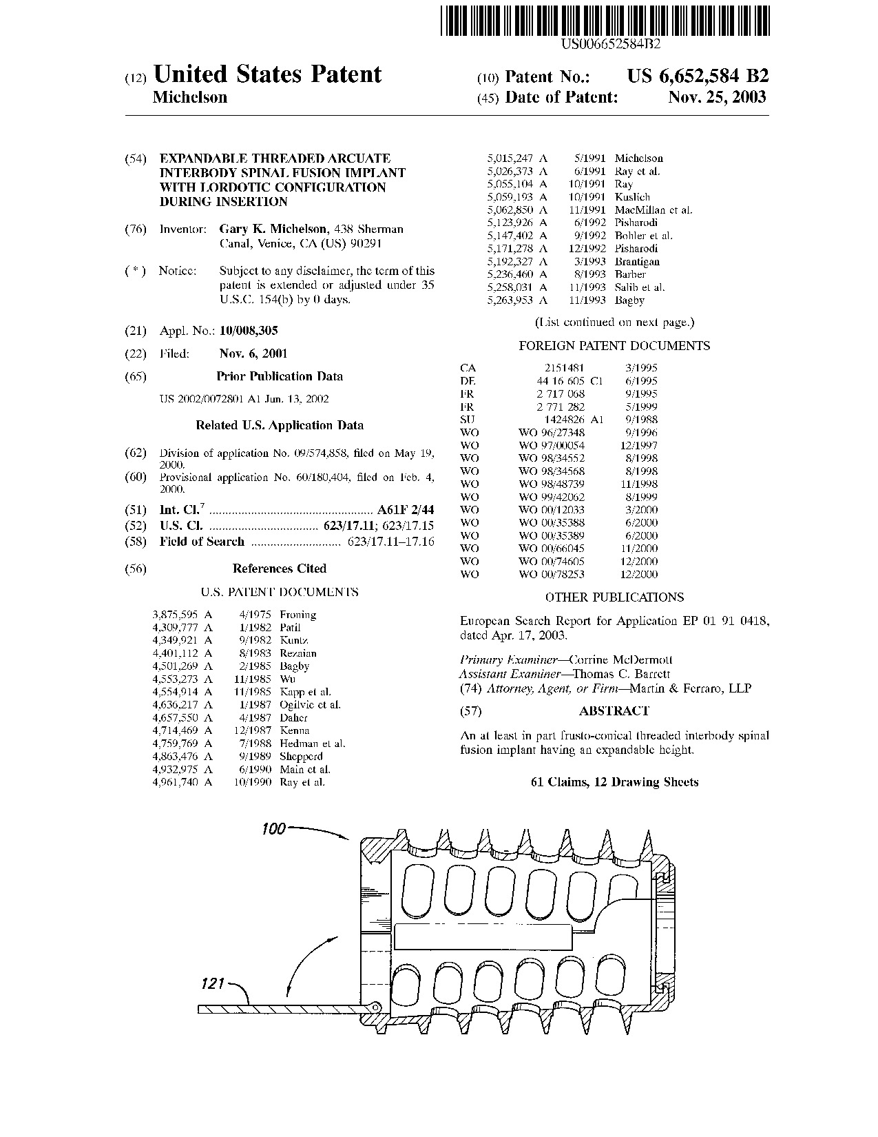 Expandable threaded arcuate interbody spinal fusion implant with lordotic configuration during insertion - Patent 6,652,584 Expandable threaded arcuate interbody spinal fusion implant with lordotic configuration during insertion - Patent 6,652,584
|
An at least in part frusto-conical threaded interbody spinal fusion implant having an expandable height.
|
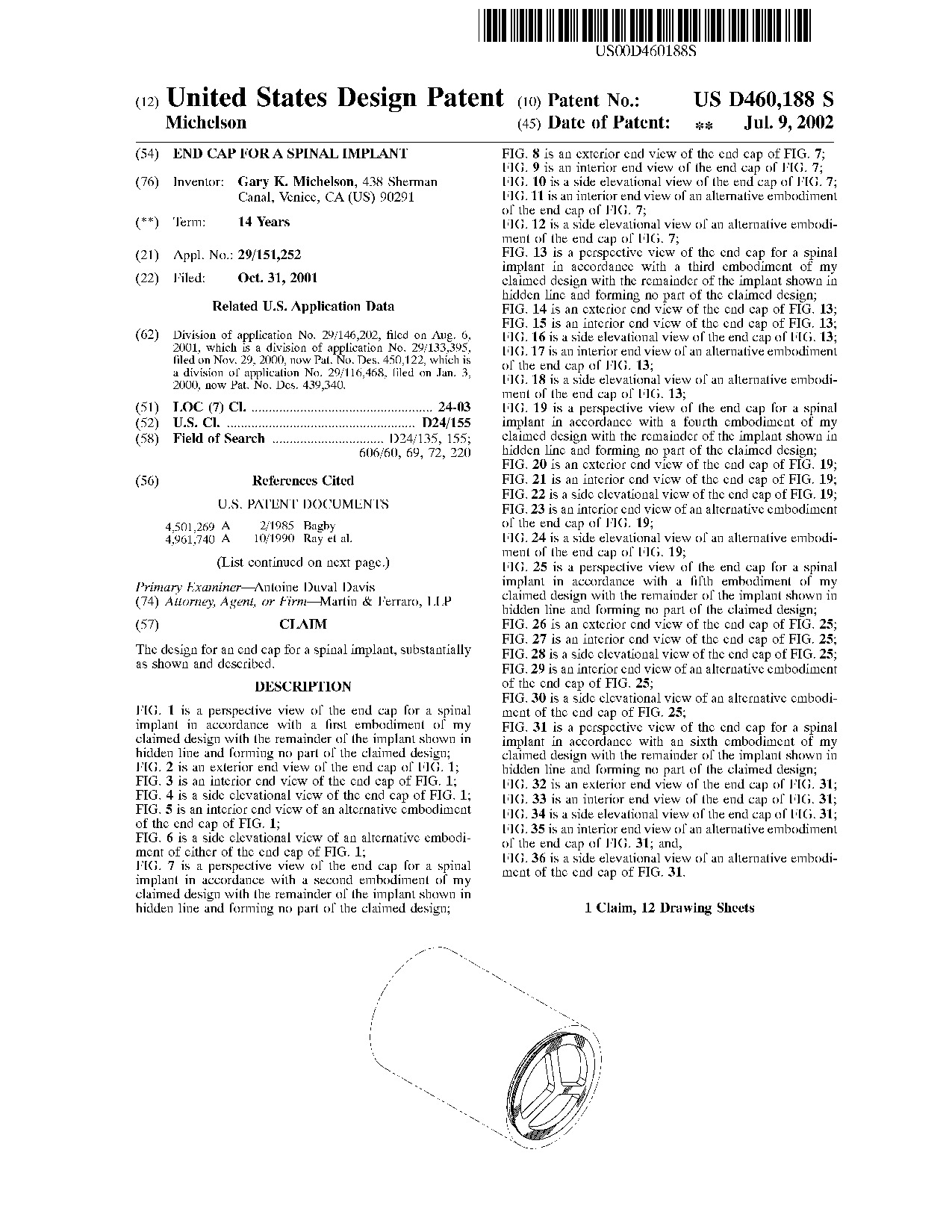 End cap for a spinal implant - Patent D460,188 End cap for a spinal implant - Patent D460,188
|
|
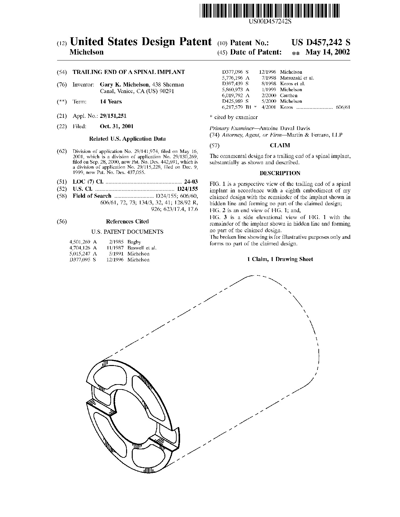 Trailing end of a spinal implant - Patent D457,242 Trailing end of a spinal implant - Patent D457,242
|
|
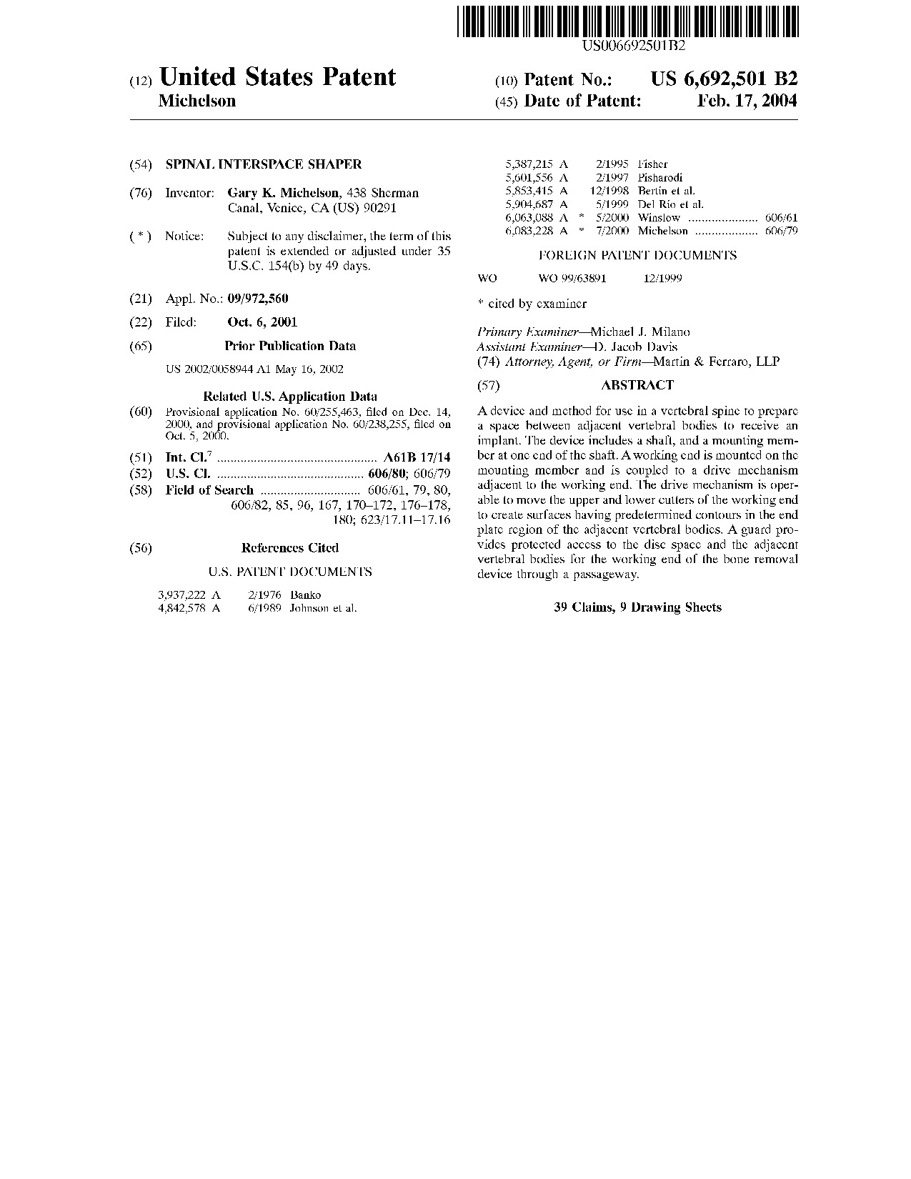 Spinal interspace shaper - Patent 6,692,501 Spinal interspace shaper - Patent 6,692,501
|
A device and method for use in a vertebral spine to prepare a space between adjacent vertebral bodies to receive an implant. The device includes a shaft, and a mounting member at one end of the shaft. A working end is mounted on the mounting member and is coupled to a drive mechanism adjacent to the working end. The drive mechanism is operable to move the upper and lower cutters of the working end to create surfaces having predetermined contours in the end plate region of the adjacent vertebral bodies. A guard provides protected access to the disc space and the adjacent vertebral bodies for the working end of the bone removal device through a passageway.
|
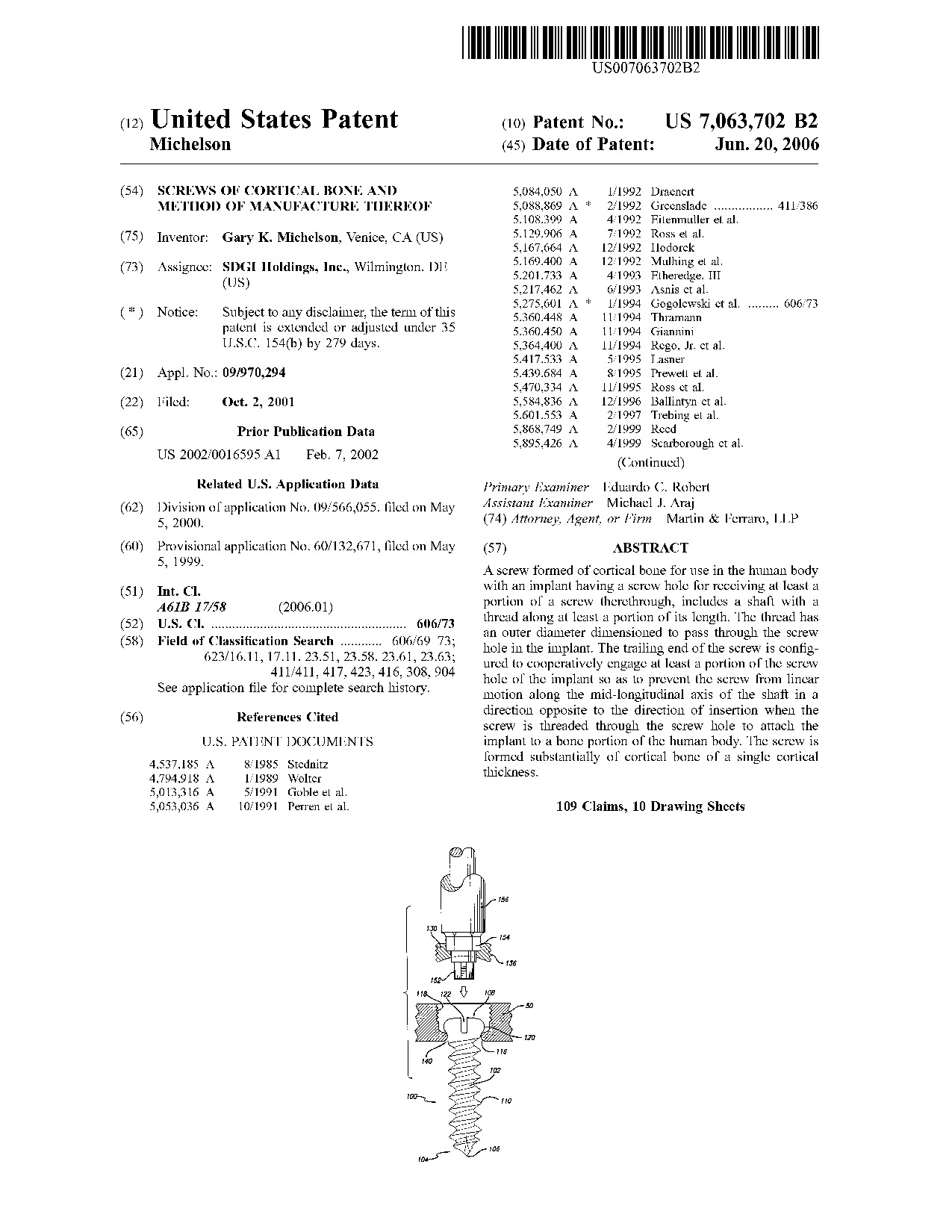 Screws of cortical bone and method of manufacture thereof - Patent 7,063,702 Screws of cortical bone and method of manufacture thereof - Patent 7,063,702
|
A screw formed of cortical bone for use in the human body with an implant having a screw hole for receiving at least a portion of a screw therethrough, includes a shaft with a thread along at least a portion of its length. The thread has an outer diameter dimensioned to pass through the screw hole in the implant. The trailing end of the screw is configured to cooperatively engage at least a portion of the screw hole of the implant so as to prevent the screw from linear motion along the mid-longitudinal axis of the shaft in a direction opposite to the direction of insertion when the screw is threaded through the screw hole to attach the implant to a bone portion of the human body. The screw is formed substantially of cortical bone of a single cortical thickness.
|
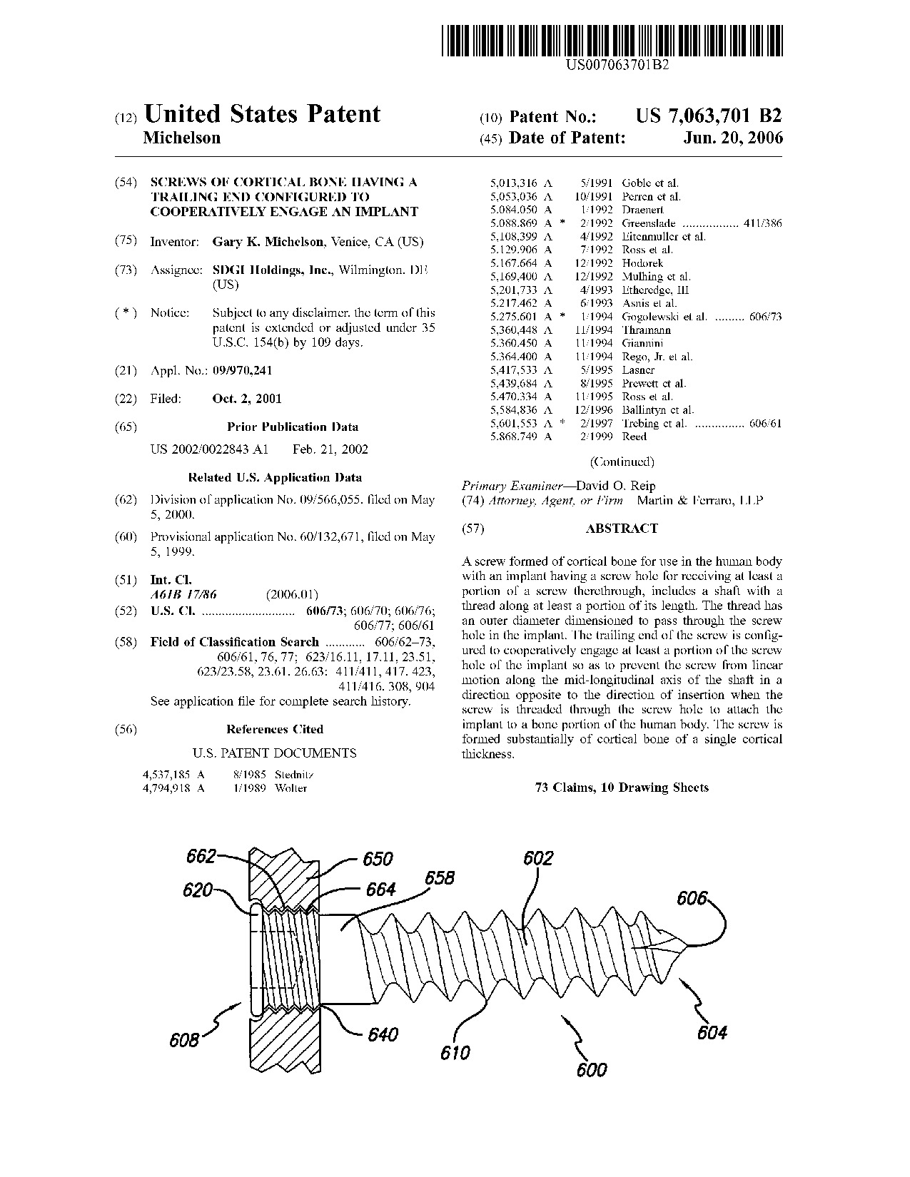 Screws of cortical bone having a trailing end configured to cooperatively engage an implant - Patent 7,063,701 Screws of cortical bone having a trailing end configured to cooperatively engage an implant - Patent 7,063,701
|
A screw formed of cortical bone for use in the human body with an implant having a screw hole for receiving at least a portion of a screw therethrough, includes a shaft with a thread along at least a portion of its length. The thread has an outer diameter dimensioned to pass through the screw hole in the implant. The trailing end of the screw is configured to cooperatively engage at least a portion of the screw hole of the implant so as to prevent the screw from linear motion along the mid-longitudinal axis of the shaft in a direction opposite to the direction of insertion when the screw is threaded through the screw hole to attach the implant to a bone portion of the human body. The screw is formed substantially of cortical bone of a single cortical thickness.
|
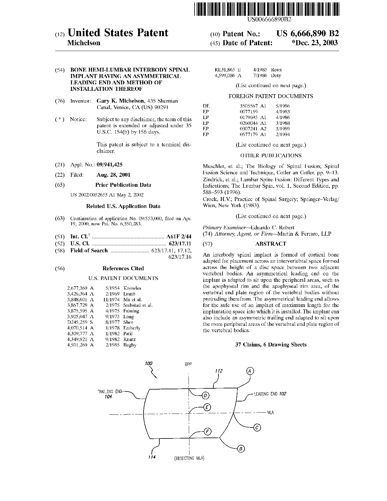 Bone hemi-lumbar interbody spinal implant having an asymmetrical leading end and method of installation thereof - Patent 6,666,890 Bone hemi-lumbar interbody spinal implant having an asymmetrical leading end and method of installation thereof - Patent 6,666,890
|
An interbody spinal implant is formed of cortical bone adapted for placement across an intervertebral space formed across the height of a disc space between two adjacent vertebral bodies. An asymmetrical leading end on the implant is adapted to sit upon the peripheral areas, such as the apophyseal rim and the apophyseal rim area, of the vertebral end plate region of the vertebral bodies without protruding therefrom. The asymmetrical leading end allows for the safe use of an implant of maximum length for the implantation space into which it is installed. The implant can also include an asymmetric trailing end adapted to sit upon the more peripheral areas of the vertebral end plate region of the vertebral bodies.
|
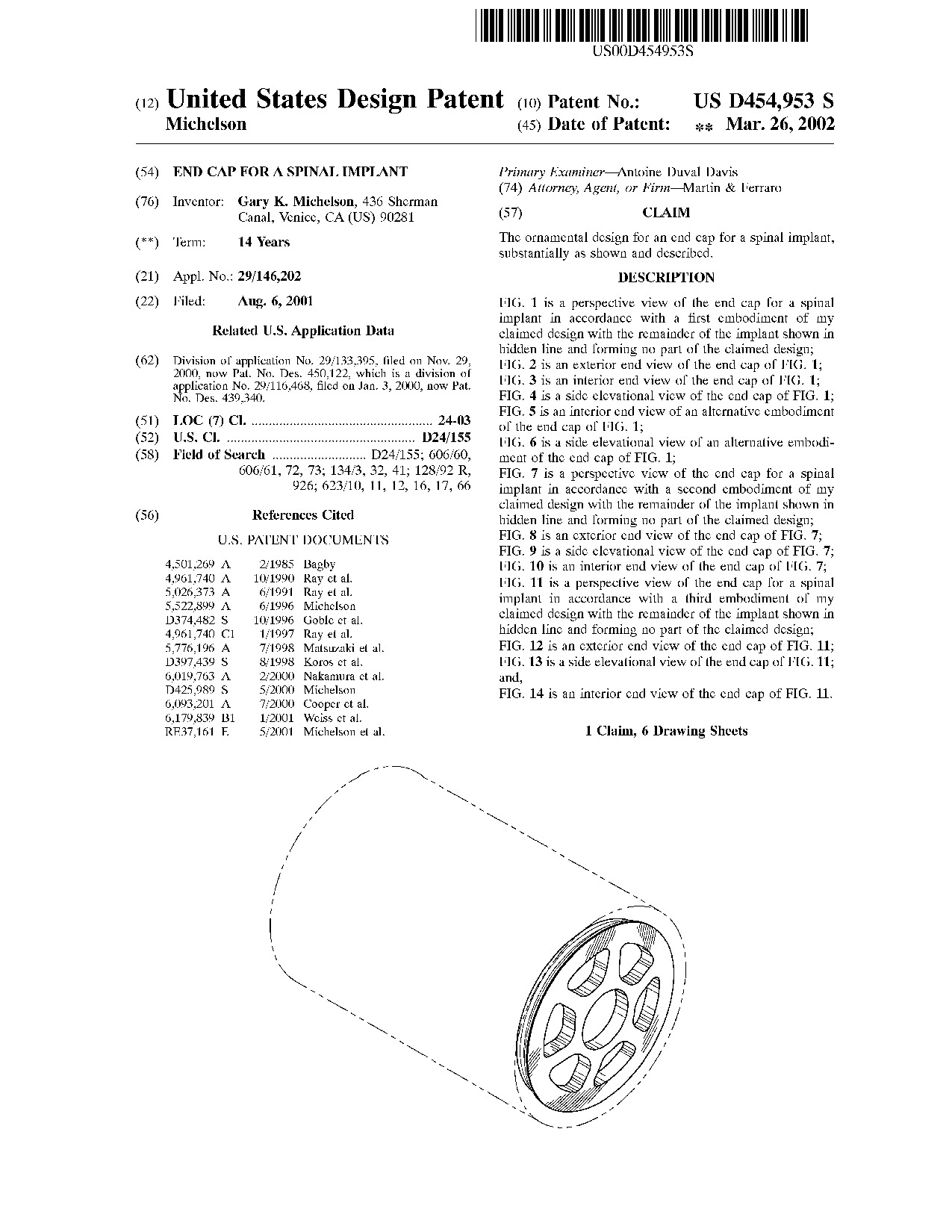 End cap for a spinal implant - Patent D454,953 End cap for a spinal implant - Patent D454,953
|
|
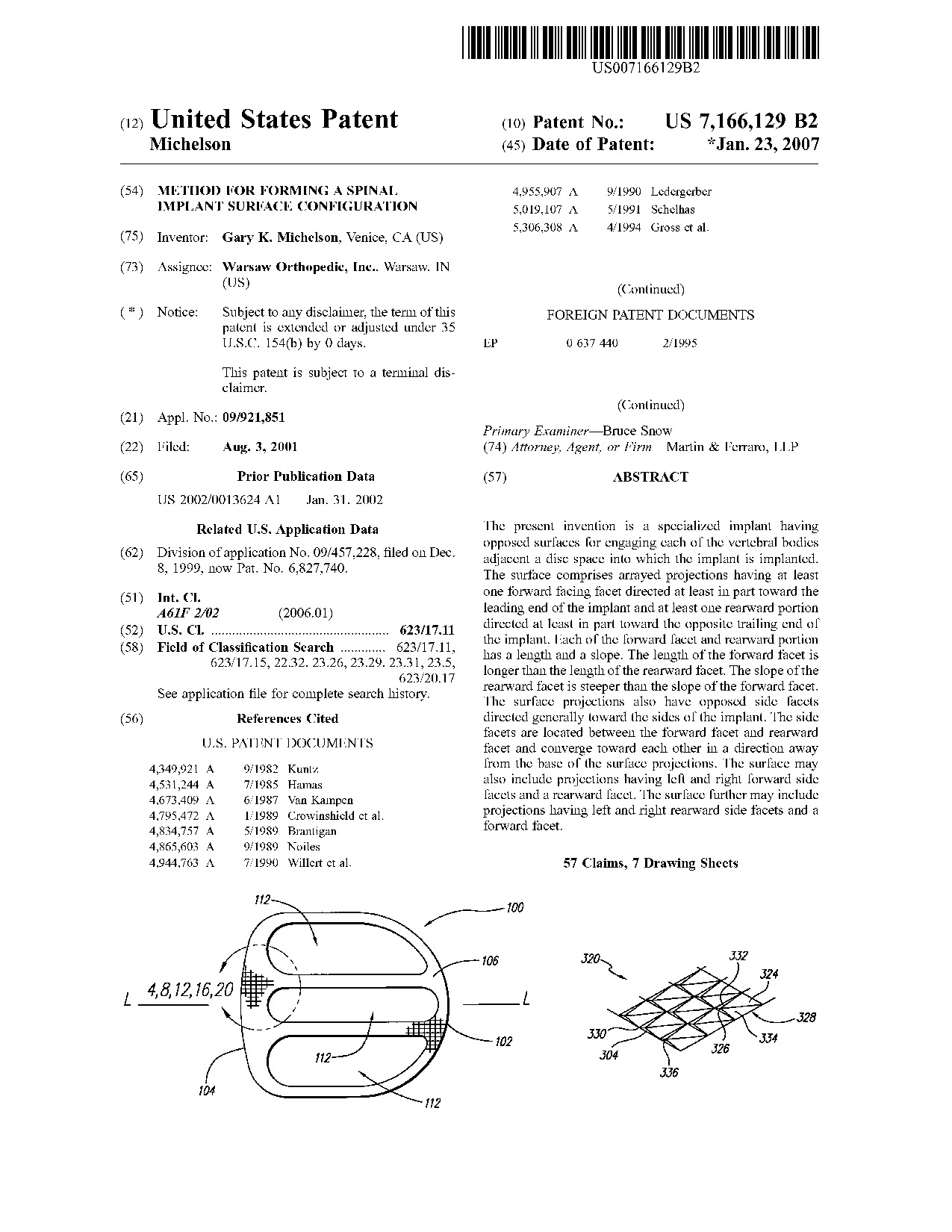 Method for forming a spinal implant surface configuration - Patent 7,166,129 Method for forming a spinal implant surface configuration - Patent 7,166,129
|
The present invention is a specialized implant having opposed surfaces for engaging each of the vertebral bodies adjacent a disc space into which the implant is implanted. The surface comprises arrayed projections having at least one forward facing facet directed at least in part toward the leading end of the implant and at least one rearward portion directed at least in part toward the opposite trailing end of the implant. Each of the forward facet and rearward portion has a length and a slope. The length of the forward facet is longer than the length of the rearward facet. The slope of the rearward facet is steeper than the slope of the forward facet. The surface projections also have opposed side facets directed generally toward the sides of the implant. The side facets are located between the forward facet and rearward facet and converge toward each other in a direction away from the base of the surface projections. The surface may also include projections having left and right forward side facets and a rearward facet. The surface further may include projections having left and right rearward side facets and a forward facet.
|
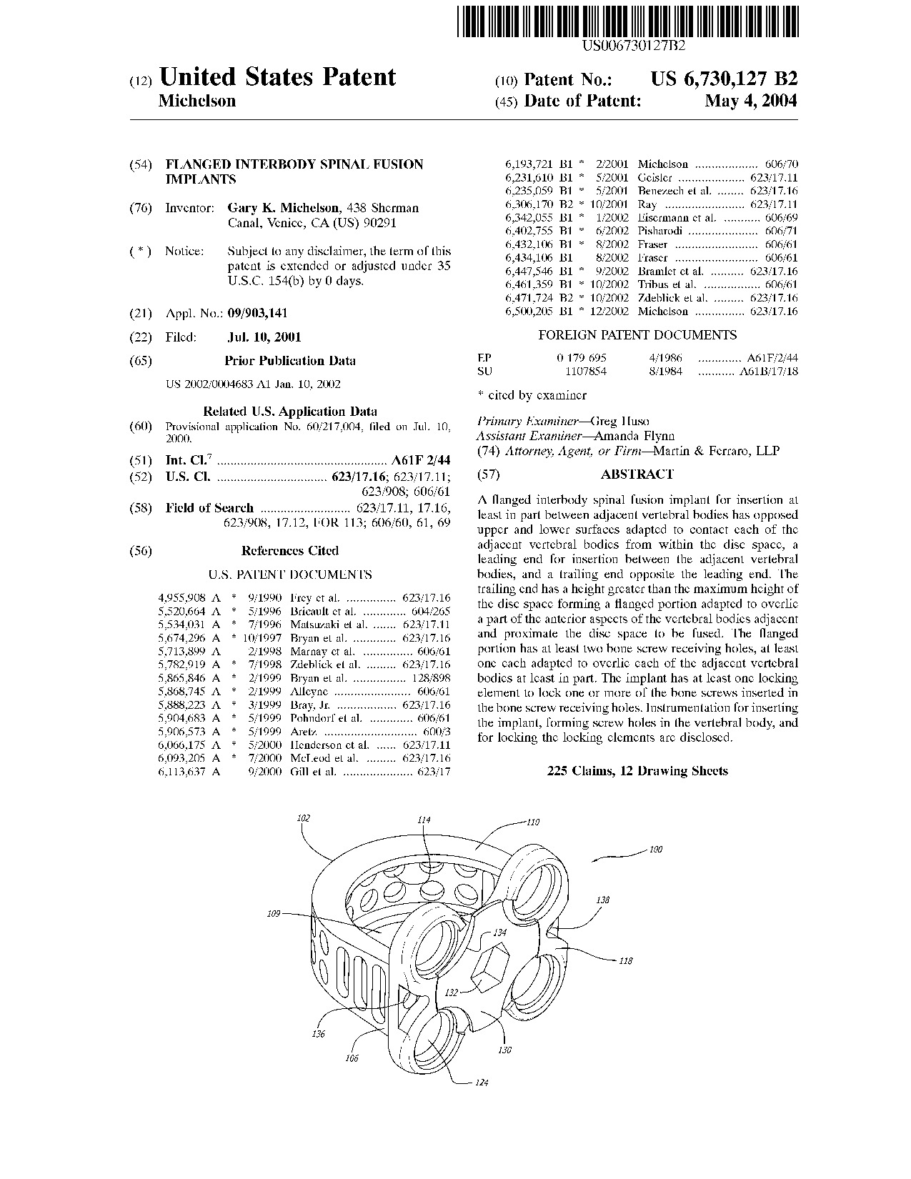 Flanged interbody spinal fusion implants - Patent 6,730,127 Flanged interbody spinal fusion implants - Patent 6,730,127
|
A flanged interbody spinal fusion implant for insertion at least in part between adjacent vertebral bodies has opposed upper and lower surfaces adapted to contact each of the adjacent vertebral bodies from within the disc space, a leading end for insertion between the adjacent vertebral bodies, and a trailing end opposite the leading end. The trailing end has a height greater than the maximum height of the disc space forming a flanged portion adapted to overlie a part of the anterior aspects of the vertebral bodies adjacent and proximate the disc space to be fused. The flanged portion has at least two bone screw receiving holes, at least one each adapted to overlie each of the adjacent vertebral bodies at least in part. The implant has at least one locking element to lock one or more of the bone screws inserted in the bone screw receiving holes. Instrumentation for inserting the implant, forming screw holes in the vertebral body, and for locking the locking elements are disclosed.
|
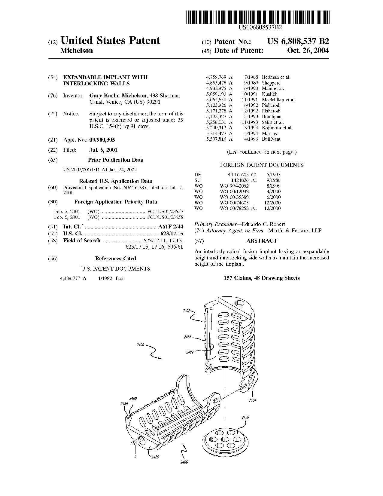 Expandable implant with interlocking walls - Patent 6,808,537 Expandable implant with interlocking walls - Patent 6,808,537
|
An interbody spinal fusion implant having an expandable height and interlocking side walls to maintain the increased height of the implant.
|
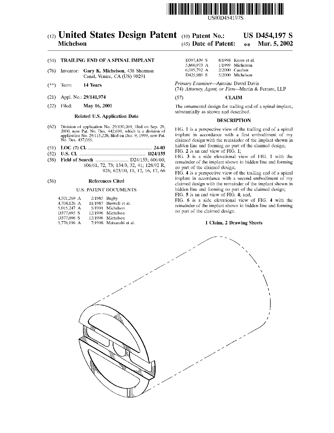 Trailing end of a spinal implant - Patent D454,197 Trailing end of a spinal implant - Patent D454,197
|
|
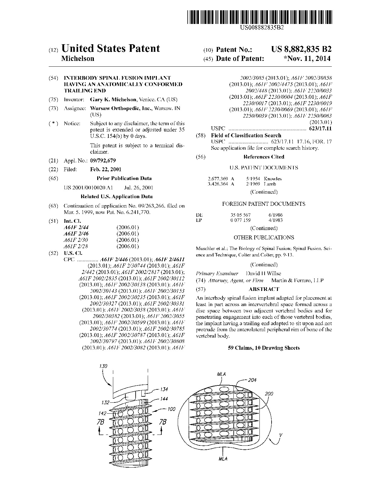 Interbody spinal fusion implant having an anatomically conformed trailing end - Patent 8,882,835 Interbody spinal fusion implant having an anatomically conformed trailing end - Patent 8,882,835
|
An interbody spinal fusion implant adapted for placement at least in part across an intervertebral space formed across a disc space between two adjacent vertebral bodies and for penetrating engagement into each of those vertebral bodies, the implant having a trailing end adapted to sit upon and not protrude from the anterolateral peripheral rim of bone of the vertebral body.
|
 Surgical rongeur - Patent 6,695,849 Surgical rongeur - Patent 6,695,849
|
An improved multi-bite bone cutting rongeur with an ultrathin foot plate and a disposable cutting element and storage chamber unit. The present invention has an integrated cutting element and storage chamber unit that is truly disposable, rather than merely replaceable. The present invention requires the use of no tools or special assembly. The chamber is simply placed onto the shaft whereby it is immediately locked into place by the use of the instrument.
|
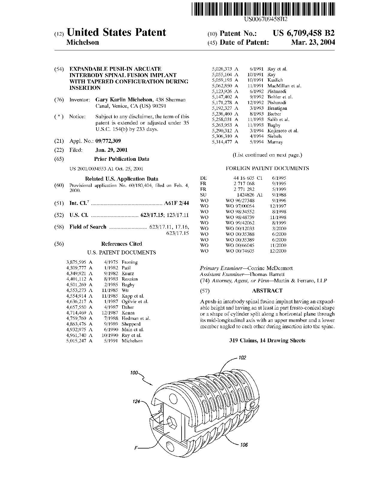 Expandable push-in arcuate interbody spinal fusion implant with tapered configuration during insertion - Patent 6,709,458 Expandable push-in arcuate interbody spinal fusion implant with tapered configuration during insertion - Patent 6,709,458
|
A push-in interbody spinal fusion implant having an expandable height and having an at least in part frusto-conical shape or a shape of cylinder split along a horizontal plane through its mid-longitudinal axis with an upper member and a lower member angled to each other during insertion into the spine.
|
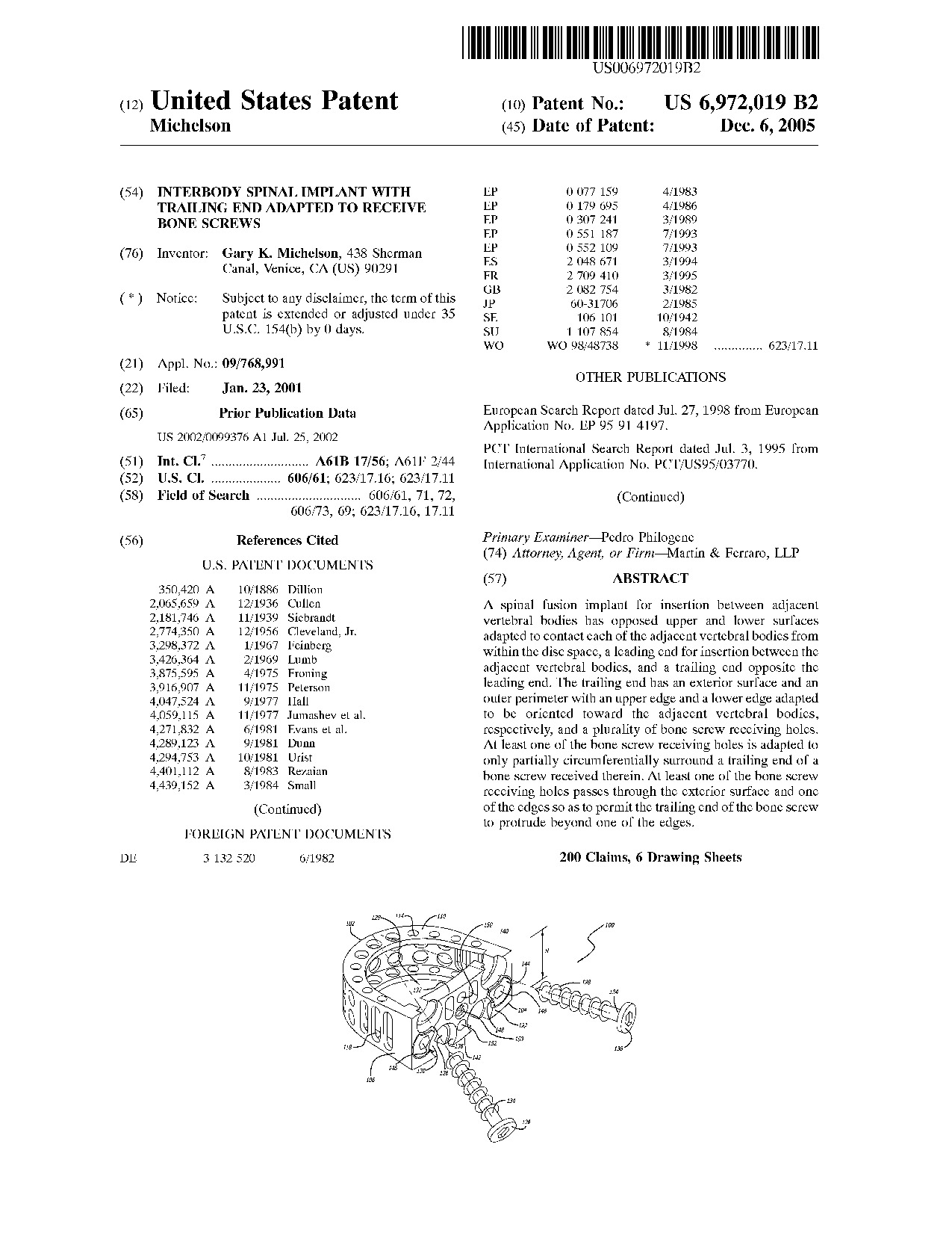 Interbody spinal implant with trailing end adapted to receive bone screws - Patent 6,972,019 Interbody spinal implant with trailing end adapted to receive bone screws - Patent 6,972,019
|
A spinal fusion implant for insertion between adjacent vertebral bodies has opposed upper and lower surfaces adapted to contact each of the adjacent vertebral bodies from within the disc space, a leading end for insertion between the adjacent vertebral bodies, and a trailing end opposite the leading end. The trailing end has an exterior surface and an outer perimeter with an upper edge and a lower edge adapted to be oriented toward the adjacent vertebral bodies, respectively, and a plurality of bone screw receiving holes. At least one of the bone screw receiving holes is adapted to only partially circumferentially surround a trailing end of a bone screw received therein. At least one of the bone screw receiving holes passes through the exterior surface and one of the edges so as to permit the trailing end of the bone screw to protrude beyond one of the edges.
|
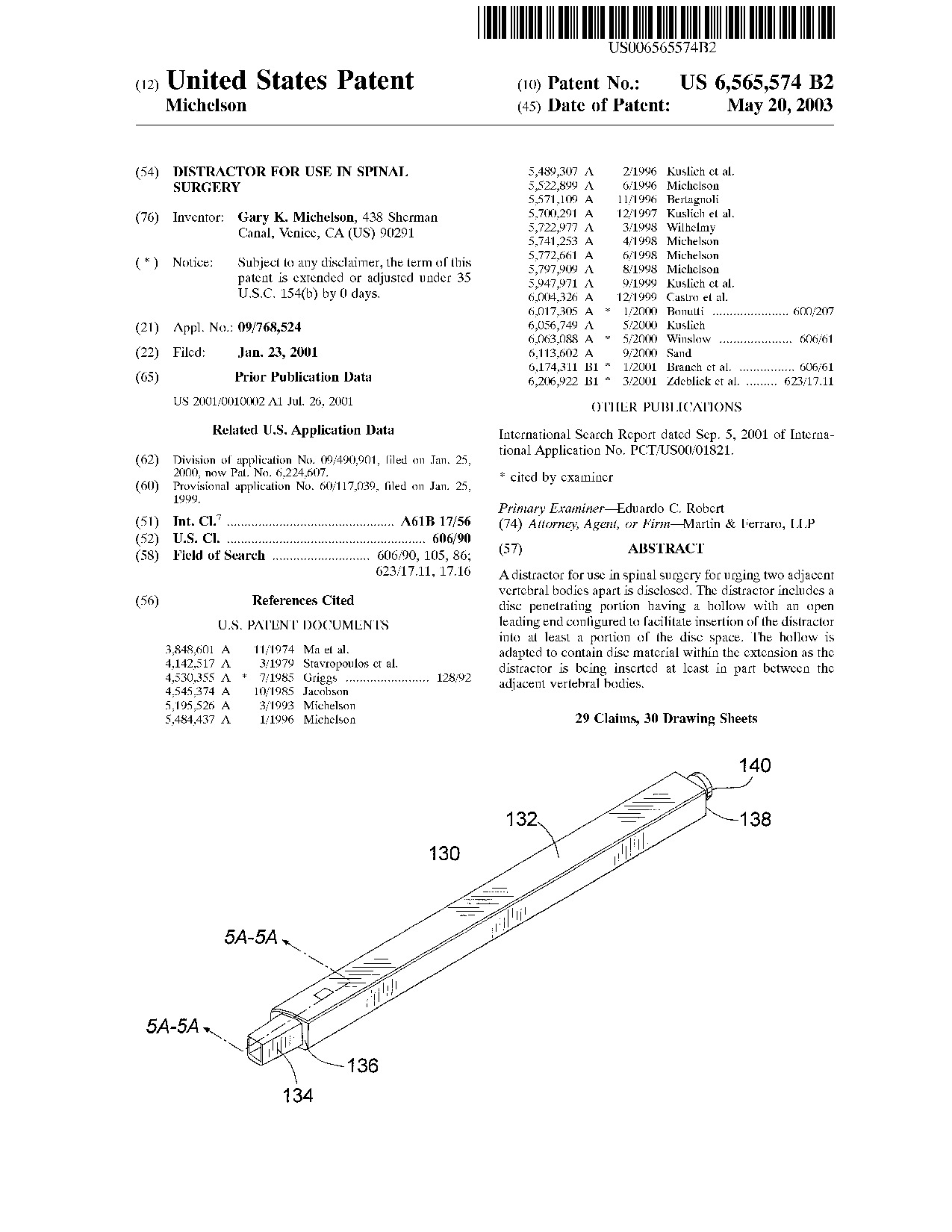 Distractor for use in spinal surgery - Patent 6,565,574 Distractor for use in spinal surgery - Patent 6,565,574
|
A distractor for use in spinal surgery for urging two adjacent vertebral bodies apart is disclosed. The distractor includes a disc penetrating portion having a hollow with an open leading end configured to facilitate insertion of the distractor into at least a portion of the disc space. The hollow is adapted to contain disc material within the extension as the distractor is being inserted at least in part between the adjacent vertebral bodies.
|
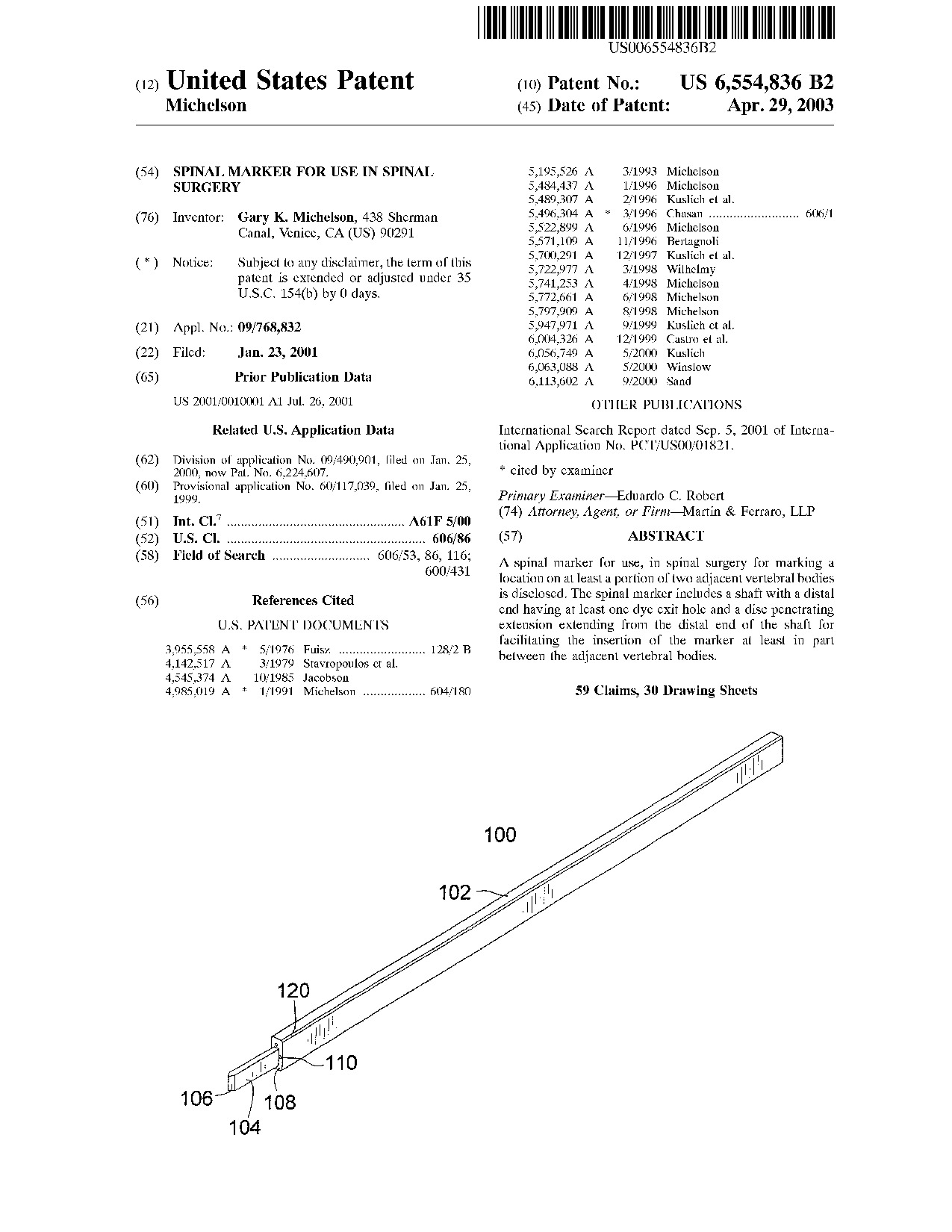 Spinal marker for use in spinal surgery - Patent 6,554,836 Spinal marker for use in spinal surgery - Patent 6,554,836
|
A spinal marker for use, in spinal surgery for marking a location on at least a portion of two adjacent vertebral bodies is disclosed. The spinal marker includes a shaft with a distal end having at least one dye exit hole and a disc penetrating extension extending from the distal end of the shaft for facilitating the insertion of the marker at least in part between the adjacent vertebral bodies.
|
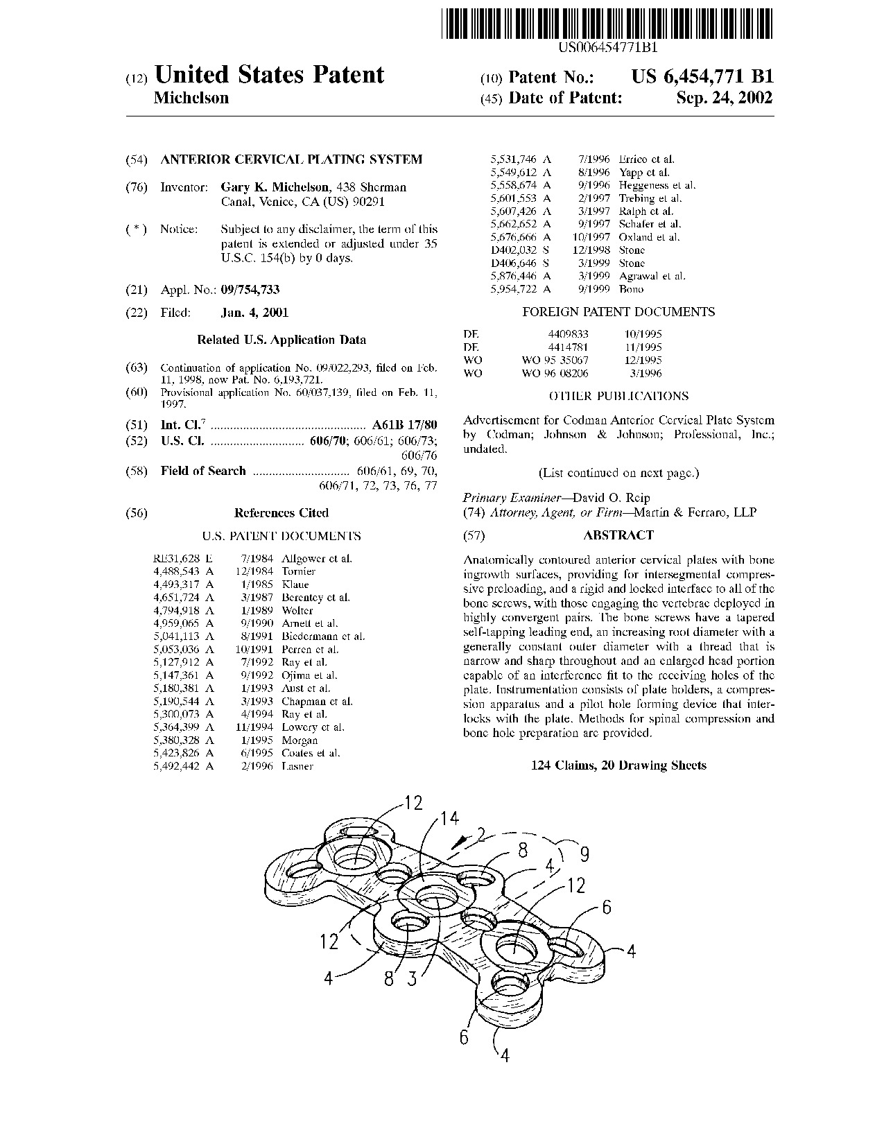 Anterior cervical plating system - Patent 6,454,771 Anterior cervical plating system - Patent 6,454,771
|
Anatomically contoured anterior cervical plates with bone ingrowth surfaces, providing for intersegmental compressive preloading, and a rigid and locked interface to all of the bone screws, with those engaging the vertebrae deployed in highly convergent pairs. The bone screws have a tapered self-tapping leading end, an increasing root diameter with a generally constant outer diameter with a thread that is narrow and sharp throughout and an enlarged head portion capable of an interference fit to the receiving holes of the plate. Instrumentation consists of plate holders, a compression apparatus and a pilot hole forming device that interlocks with the plate. Methods for spinal compression and bone hole preparation are provided.
|